Project Realisation
NOTES:
- All measurements are in millimetres (mm) - including diagrams
- Extra pieces were made in case. Not all of them were used.
- Acrylic was sanded and polished with the following process unless stated otherwise: 80 & 120 grade sandpaper, wet and dry paper, brasso.
- Markings were done with a ruler, tri-square and scribe or pencil, depending which material was being marked.
- During the construction of the Tent Frame there are a lack of pictures, because I didn't bring my phone to school for a couple of weeks. To make up for this I made some diagrams to help with explanations.
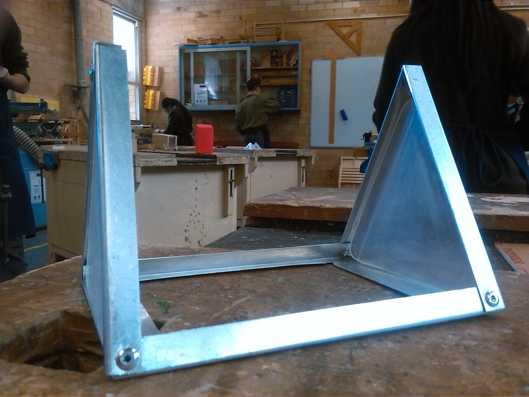
Construction of Tent Frame
The construction of the tent frame is made of a combination of aluminium and and acrylic.
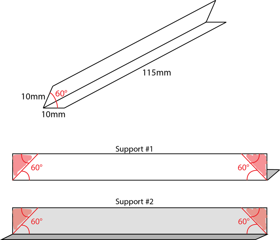
The pieces needed for the frame were first marked out on the aluminium sheet: 6x 20 by 115 (support) ; 2x 10 by 150 mm (spine) ; 1x 130 by 150 mm (base). They were then given to the teacher to be cut on the guillotine.
The construction of the tent frame is made of a combination of aluminium and and acrylic.
The pieces needed for the frame were first marked out on the aluminium sheet: 6x 20 by 115 (support) ; 2x 10 by 150 mm (spine) ; 1x 130 by 150 mm (base). They were then given to the teacher to be cut on the guillotine.
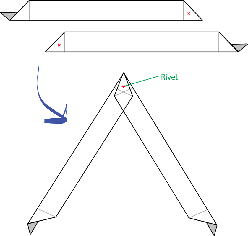
The support pieces were then bent along the longer side at approximately 60° (changes could be made later). Then the support pieces were paired up and marked like shown in the diagram. Using tinsnips, the red sections of the support pieces were snipped off. The pairs were then arranged and marked like the diagram. With great difficulty, as I hadn't thought of this when I bent it, and now it was too late, I center-punched and drilled a 5.5 ⌀ hole on the red x's marked in the diagram. When drilling I used a block of timber under the piece to support it and the drill vice to help secure it. After the holes were drilled, a larger sized drillbit was used to reverse drill and remove the uplift. The pairs were placed together like shown in the diagram and then riveted together.
|
|
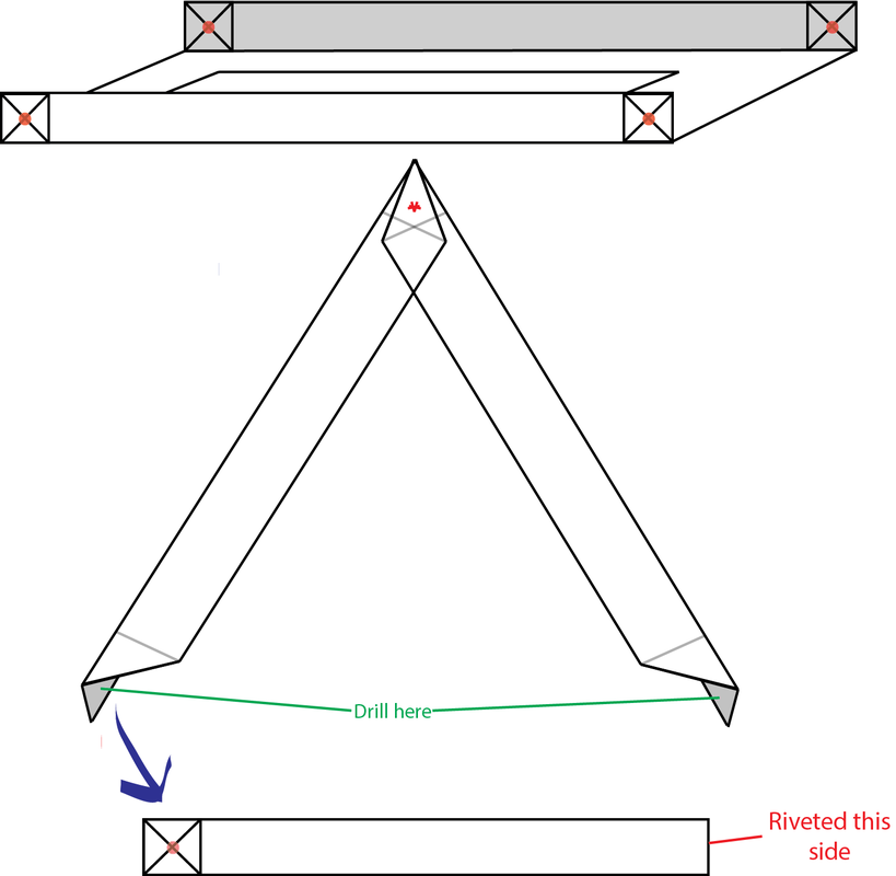
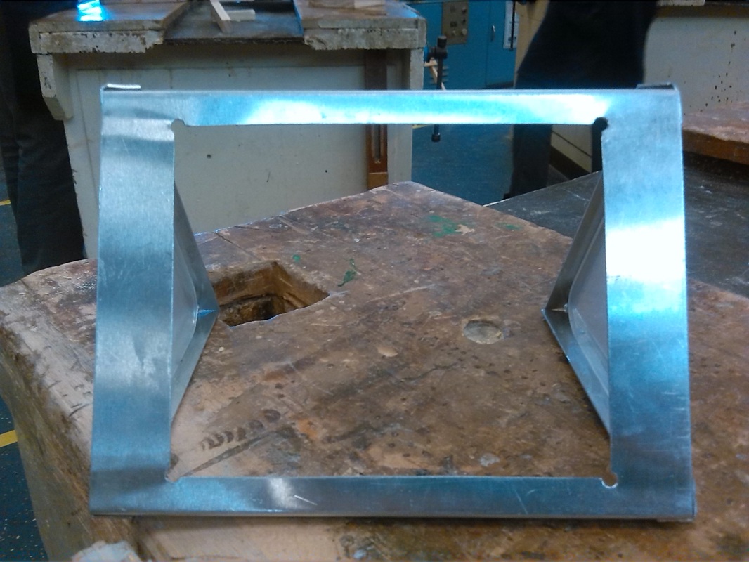
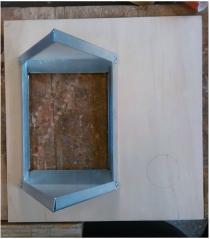
The base was made by measuring a 90 x 110 hole in the very centre of the base. The corner were then drilled and the panel was scroll sawed out. I deliberately decided to cut in the lines I drew as I would file it down more accurately later. Ensuring that it would be straight and it would line up when I filed the metal down, I sandwiched the aluminium between two strips of timber, where the edges of the timber lined up with the marking. Thus when filing, all I had to do was file down to the timber, and the timber would stop me from over-filing and help me file an even straight line. after it was filed down, I used a small file and some wet and dry paper to smooth the edges down. After I measured 10 in from the 130 side of the aluminium. and folded it approximately 90° up along this marked line. The both of the folded up sides were marked like shown in the diagram. The riveted supports were also then marked like shown in the diagram. Now came a rather difficult part, which was a result of me not thinking ahead. In order to drill the hole it required quite a lot of working around things as, they were tilted at funny angles. In the end I manages to drill the holes, by supporting it in the drill vice and layered blocks of timber. After the holes were drilled I assembled the tent like shown in the pictures and riveted the holes. Most of the holes matches up quite nicely except for one, but it was didn't cause too much worry as in the end the rivet was still able to go through but it ended up being slightly lopsided.
I decided to not use the spine piece later on during the construction as I thought it was support that wasn't needed and I discovered it couldn't be securely supported onto the rest of the frame as the surface area for the rivet was too small.
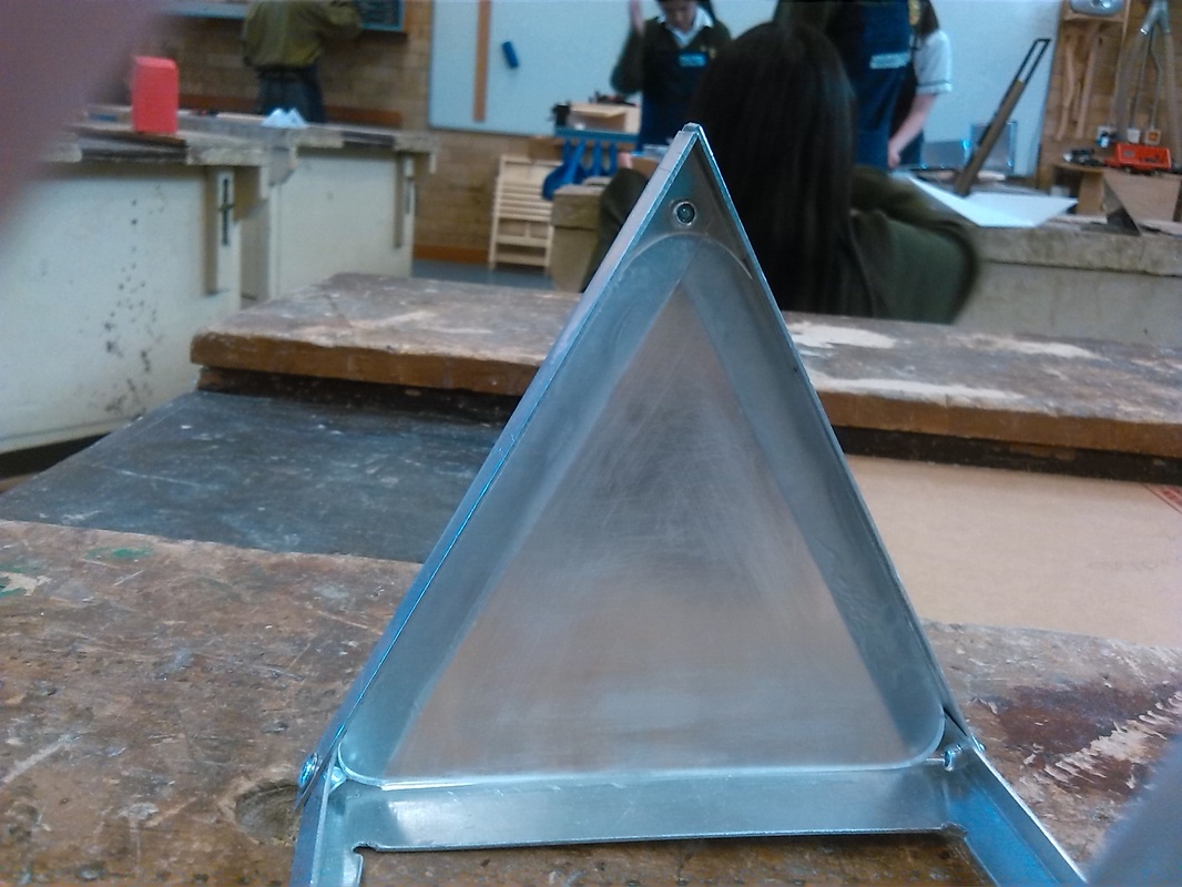
Frosted triangular acrylic with the rounded sides
|
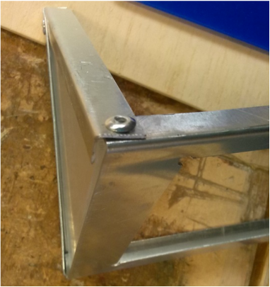
The slightly lopsided rivet
|
Once the frame was done I started on the acrylic pieces. The frame consists of 3 parts of acrylic: 2 triangular frosted acrylics like shown in the above left picture and a blue acrylic piece that will be play in the base and hold the plug for the LED.
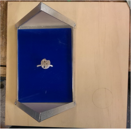
The frosted piece was first marked out on a sheet of clear acrylic like the diagram shown below. Using a scroll saw I the roughly cut out two triangles. The sides were then desanded and polished. After I polished it, I peeled of one side of the protective covering and used a piece of wet and dry paper to frost one side of the clear acrylic until I was satisfied with the result. This was then done to the other acrylic triangle. Now it was pushed into the frame, but then I discovered even if it was a tight fit, it couldn't be securely bonded to the frame with epoxy as the rivets blocked the piece from being fully pushed in,and being attached to the frame. And so, through trial and error I rounded the edges of the triangular pieces on the desander, like shown in the picture, until the pieces fit snugly into the frame. After I found the fit, a polished the sides again and used epoxy to bond the frame to the acrylic.
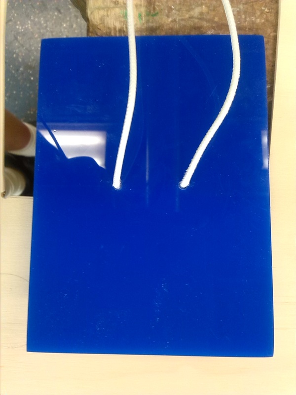
The blue acrylic piece was done with the same process, marking a 100 x 130 on the acrylic and cutting it out on the scroll saw, I then desanded down the sided and polished the sides. After using a scribe, since I had already peeled of the protective covering, I marked two drill holes like shown in the diagram. Using a 4.5 ⌀ drillbit, drilled the holes for the plug to got through. Once the hole was drilled, I made sure the the plug was able to fit and then I bonded this piece to the frame using epoxy. After, I secured the plug to the acrylic with a hot glue gun.
The frosted piece was first marked out on a sheet of clear acrylic like the diagram shown below. Using a scroll saw I the roughly cut out two triangles. The sides were then desanded and polished. After I polished it, I peeled of one side of the protective covering and used a piece of wet and dry paper to frost one side of the clear acrylic until I was satisfied with the result. This was then done to the other acrylic triangle. Now it was pushed into the frame, but then I discovered even if it was a tight fit, it couldn't be securely bonded to the frame with epoxy as the rivets blocked the piece from being fully pushed in,and being attached to the frame. And so, through trial and error I rounded the edges of the triangular pieces on the desander, like shown in the picture, until the pieces fit snugly into the frame. After I found the fit, a polished the sides again and used epoxy to bond the frame to the acrylic.
The blue acrylic piece was done with the same process, marking a 100 x 130 on the acrylic and cutting it out on the scroll saw, I then desanded down the sided and polished the sides. After using a scribe, since I had already peeled of the protective covering, I marked two drill holes like shown in the diagram. Using a 4.5 ⌀ drillbit, drilled the holes for the plug to got through. Once the hole was drilled, I made sure the the plug was able to fit and then I bonded this piece to the frame using epoxy. After, I secured the plug to the acrylic with a hot glue gun.

|


|


Construction of Tent Base
Relatively easy to construct. A piece of plywood that was marked with the dimensions of 225 x 235. It was then cut by the teacher and quickly sanded all over. The it was marked like shown in the diagram. In the corner of the markings, I used a nail punch and then a 5.5 ⌀ drillbit was used to drill a hole in each corner. Then I threaded the scroll saw and cut out the piece leaving the hole. Implying the same filinf technique I used for the construction of the tent frame, I filed the plywood down to the line. Once all the edges were done I sanded the edges and surface again.
Later on, once I finished the main base and was ready for the wiring and soldering, and the switch was secured into the board. I bonded the completed tent frame onto the wooden plywood base with epoxy.
The tent on the tent base
|
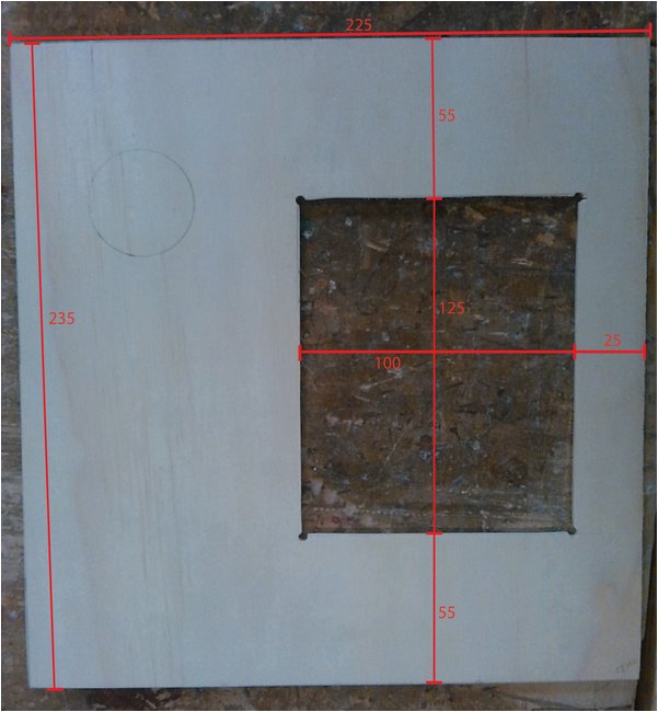
Diagram for measurements for the tent base
|

Construction of Main Base
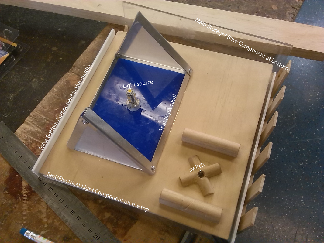
Made of plywood, acrylic and timber, the main base consists of the "false bottom" and the "storage bottom".
The false bottom is made entirely of acrylic. I started this by marking 235 x 225 on a sheet of clear acrylic, which was then cut by the teacher. This is the base of the false bottom. Originally it was to be a white sheet of acrylic until I discovered, after I had finished sanding and polishing the white piece of acrylic, that light did not shine through it well. Thus came the idea of a frosted clear acrylic alternative. After the piece of acrylic was cut, I sanded and polished the acrylic's sides. When I finished, i peeled off one side of the protective covering and using a dry wet and dry paper, rubbed the unprotected side of the acrylic until it was evenly frosted and I was satisfied with its result. After I finished this base, there were the supports of the false bottom. These were made of white acrylic and only supports two sides. Like the base, it was first measured 20 x 225 on a scrap sheet of white acrylic I found and cut using a scroll saw. I then desanded the acrylic down until it was even, which it was then polished. In order for a flat surface, to make gluing the acrylic easier and more supported; instead of using the sanding blocks in the wood tech room, as they have rounded edges, a piece of scrap timber was used as a sanding block instead as it has a flatter sharper surface, creating the desired flatness when polishing and sanding. Using epoxy I lined and glued the supports to the base as shown in the picture. In order for it to be 90° I stole some engineer's squares from the metal tech room to support and make sure it glued perpendicular to the base. I had to re-glue one of the supports later on with the stronger acrylic bond as it tipped over.
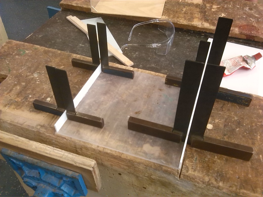
The storage bottom was made from timber, plywood and clear acrylic. First, on a piece of plywood it was measured 235 x 225 which was then cut by the teacher. I planed down the timber to the line where it was then sanded using the different grades of sand paper. I briefly sanded the surfaces of the plywood. This was the base. The supports were done like shown in the diagrams. There was a 20 wide strip of timber, that I found and I thought it would provide a stronger and more aesthetically interesting way to support the top than a plain two sides of acrylic thus it was changed from the original final prototype. On the strip of timber it was marked like shown in the diagram and then cut with a scroll saw. The ends were then desanded and then I sanded the whole thing with 120 grade sandpaper, until it was smooth but the edges were still sharp. On the base, on the 225 side, intervals of 37.5 were marked. The 6 support stems were then lined up along these intervals and stuck with PVA glue along the edge and intervals, as shown in the picture. Like done in the storage bottom, engineer squares were stolen in order to make sure the stems were glued perpendicular to the base. Some of the supports had to be re-glued as during the first glueing process, there wasn't enough glue and after it was dried when pressure was applied they snapped off. Before the side of acrylic support was glued on I gave the wood one coat of lacquer. Similar to the way the acrylic supports on the false bottom were made, 230 x 60 was marked on a piece of clear acrylic, cut, planed, sanded and polished. I decided not to frost it as I thought it clear would make it more appealing visually. During the epoxy process I encountered the problem of the bonding surface was too small and even if it stayed glued on, it would tip and be lopsided. This was overcome when I made 2 little triangular supports for it, one to support each side. Like shown in the picture, not only did it provide the support needed, but also allowed it to glue perpendicular. The block of timber is there to provide the support for the other side while the epoxy dried. And the planer is there to act as a weight to straighten out the plywood. As without it, the plywood was naturally bent in an arc. When the epoxy dried the acrylic would provide enough support for the plywood to remain flat instead of arched. After the epoxy dried another coat of lacquer was given to the wood.
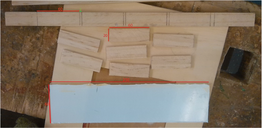
Diagram for the strorage bottom
- measurements for support stem and acrylic support


Wiring and Soldering
First I started off by inserting the switch into the tent base. In the centre of the circle I drew on the tent base (refer to pictures above in the Construction of Tent Base section) I drilled a 4.5 ⌀ hole to insert and screw in the toggle switch, which was my switch of choice. Once it was drilled and the switch was secured I proceeded with the soldering of the components. I first of all received a jack from the teacher and a LED. I did an experiment to see which light provided the best effect. I decided on the multiple LED instead of the single bulb one as the light from the multiple encompassed more of the surroundings. With this experiment it also help to test if the plug and the LED worked. After I begun the process of soldering. Before this, I had no experience in soldering as when the class did the "practice" I was away and the teacher later said that I didn't have to do it, so I learnt through the consultation of my peers and watching them do it. I thoroughly enjoyed this process as it was a very interesting new experience. I first soldered one of the plug wires to one of the terminals on the switch - I had to solder this twice as after the first time it didn't join properly, even though I thought I did. After I soldered an extra length of wire to the other plug wire as it wasn't able to reach the jack with the length that it was. After I soldered another length of wire to the centre terminal of the switch. Then I joined the end wires to the jack. I consulted with the teacher to ask if the jack could be hot glue gunned to the board of the base and he said that it wouldn't interfere with the wiring so it would be okay to carry it out. I later found out from a peer that exposed wire should be closed off via electrical tape as they would be hazardous, and so I taped up the part where I soldered the extension. I then also hot glue gunned the taped part to the board so the wires weren't hanging off the board. During the process of testing the circuit, I was discovered that the polarity had to be reversed on the transformer.
First I started off by inserting the switch into the tent base. In the centre of the circle I drew on the tent base (refer to pictures above in the Construction of Tent Base section) I drilled a 4.5 ⌀ hole to insert and screw in the toggle switch, which was my switch of choice. Once it was drilled and the switch was secured I proceeded with the soldering of the components. I first of all received a jack from the teacher and a LED. I did an experiment to see which light provided the best effect. I decided on the multiple LED instead of the single bulb one as the light from the multiple encompassed more of the surroundings. With this experiment it also help to test if the plug and the LED worked. After I begun the process of soldering. Before this, I had no experience in soldering as when the class did the "practice" I was away and the teacher later said that I didn't have to do it, so I learnt through the consultation of my peers and watching them do it. I thoroughly enjoyed this process as it was a very interesting new experience. I first soldered one of the plug wires to one of the terminals on the switch - I had to solder this twice as after the first time it didn't join properly, even though I thought I did. After I soldered an extra length of wire to the other plug wire as it wasn't able to reach the jack with the length that it was. After I soldered another length of wire to the centre terminal of the switch. Then I joined the end wires to the jack. I consulted with the teacher to ask if the jack could be hot glue gunned to the board of the base and he said that it wouldn't interfere with the wiring so it would be okay to carry it out. I later found out from a peer that exposed wire should be closed off via electrical tape as they would be hazardous, and so I taped up the part where I soldered the extension. I then also hot glue gunned the taped part to the board so the wires weren't hanging off the board. During the process of testing the circuit, I was discovered that the polarity had to be reversed on the transformer.


Construction of Tent Canvas
The construction of the tent canvas was made at home, with help and guidance from my mum.
It first started off with a a prototype using paper, which would also later act as a template. Once the prototype was confirmed and done, I folded the piece of fabric and pinned the template on like shown below. In all the templates 10mm was left for hemming and sewing. Once the fabric was marked with the hem I cut it out using the fabric scissors. The same one done for both end pieces like shown below. The pieces were then pinned together and sewn and hemmed. During this process I was under the watchful eye of my mum, as she made sure the sides were pinned correctly and I didn't make any mistakes. When adding the zipper to the tent canvas It was difficult to find a zipper short enough for tent, so my mum helped me to sew it so that the zipper would extend out the back and be the right length. After my mum hemmed the edges of the tent for me using a very complicated hemming machine, which I wasn't allowed to use.
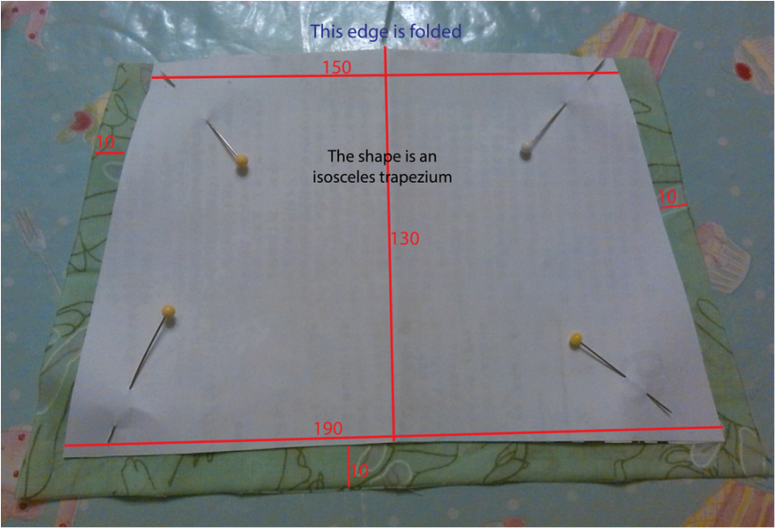
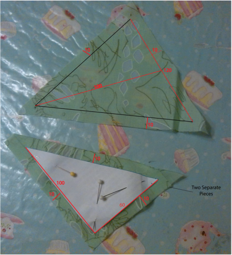
End Pieces - one is is halved and separate because a zipper is to be installed.
|
|


Assembly of Final Product
Assembly of the Final Product is yet to take place, but all components of it are essentially ready for assembly.
Assembly of the Final Product is yet to take place, but all components of it are essentially ready for assembly.